Application
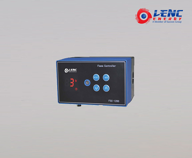
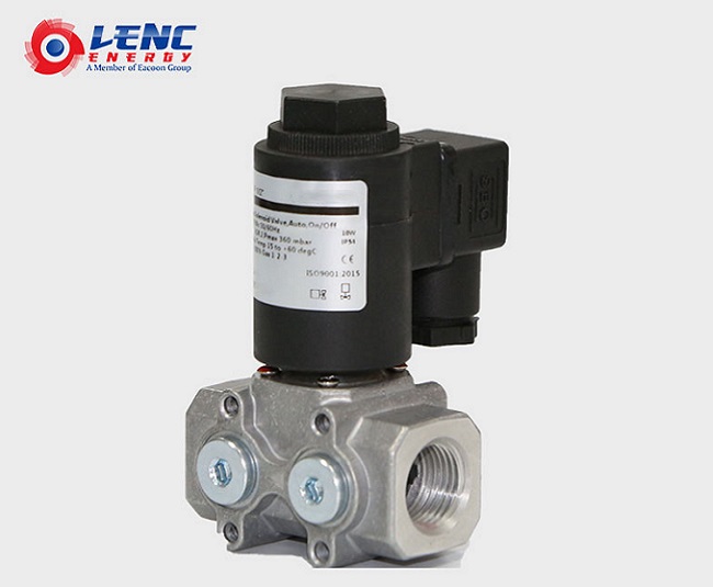
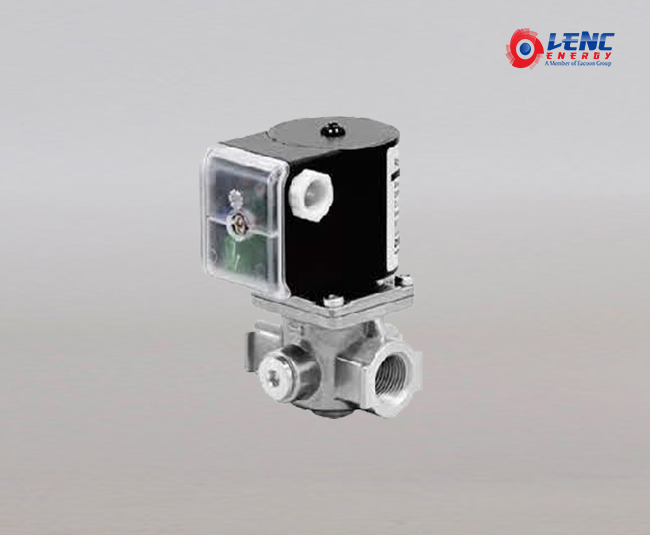
The FSC-1200 combustion controller is a high performance controller specifically designed for fuel and gas combustion control.It can be used not only for conventional combustion control, but also for a more demanding combustion environment.
This series is suitable for combustion applications of multi-burner or purge,such as ceramics, metallurgy, glass, building materials and many other industries.
Features
* 24 hours continuous operation, hundreds of thousands of operating lifetimes
* IP54 protection leverl,Apply to site or cabinet installation
* Operation status display,fault information display
* Remote or on-site reset
* Meet the European EN298 standard
The main technical parameters
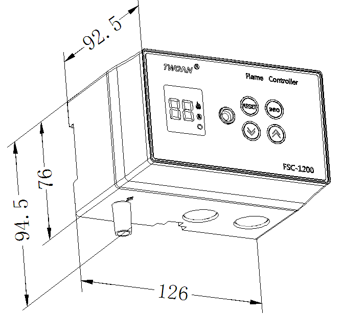
Width*thickness*height:126*94.5*92.5mm
Input voltage:AC 220V/24V 50/60Hz
Lonic bar cable length:75m (maximum)
Protection level:IP54
Environment temperature:-20℃ ~ +65℃
Environment humidity:< 95%
Operating life:>100 thousand times
The maximum current of driving the gas valve:1A ;Power factor:1
The maximum current of driving the ignition transformer:2A ;power factor:0.2
The maximum current of the output terminal:2A AC Voltage:250v
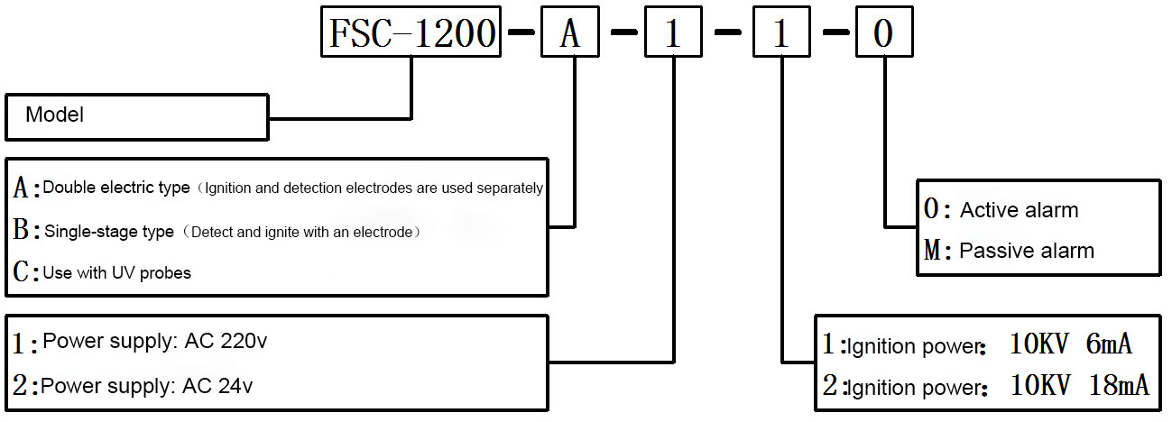
Selection table
Dimensions
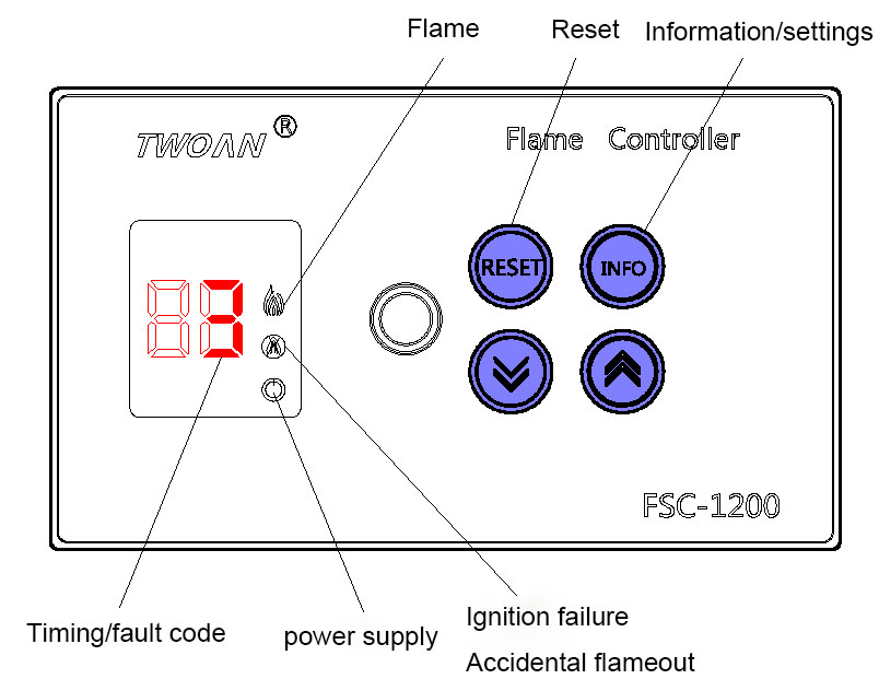
Panel description
Installation diagram
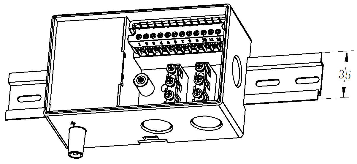
Rail installation
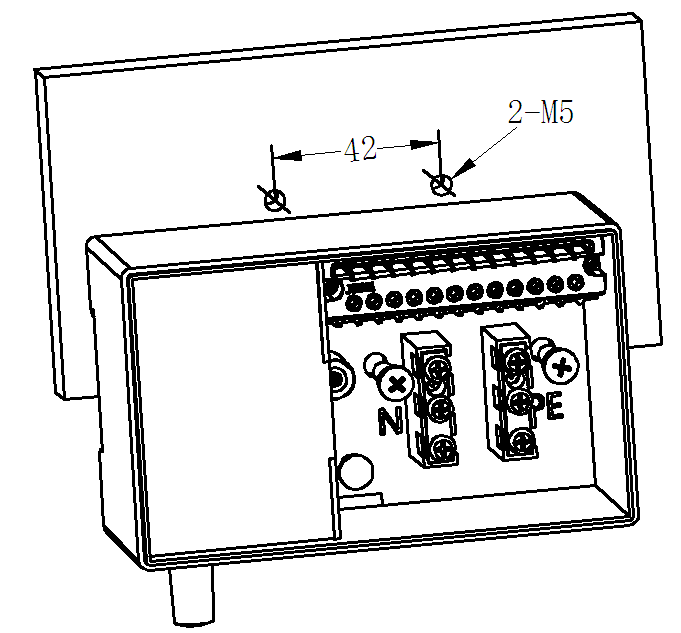
Fixing plate installation
Wiring diagram
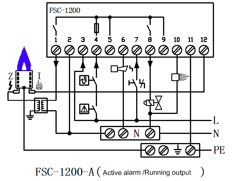
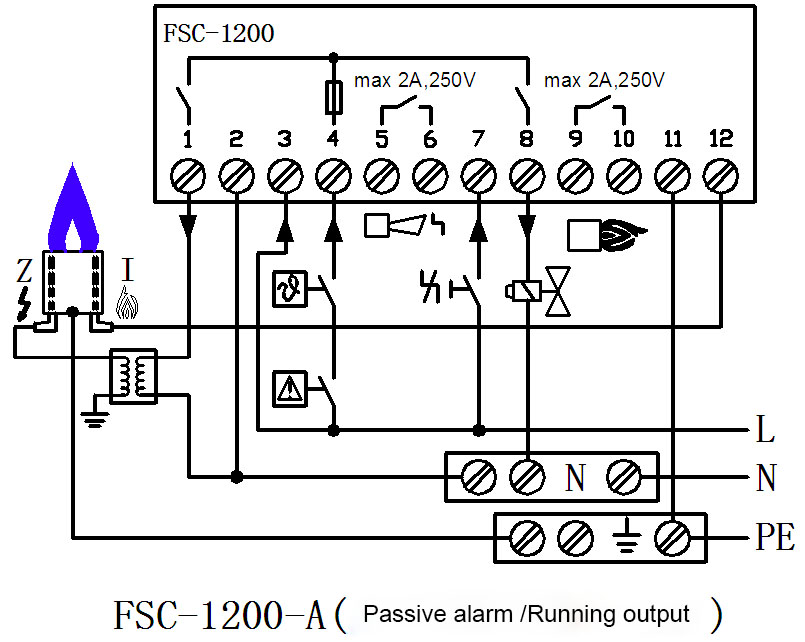
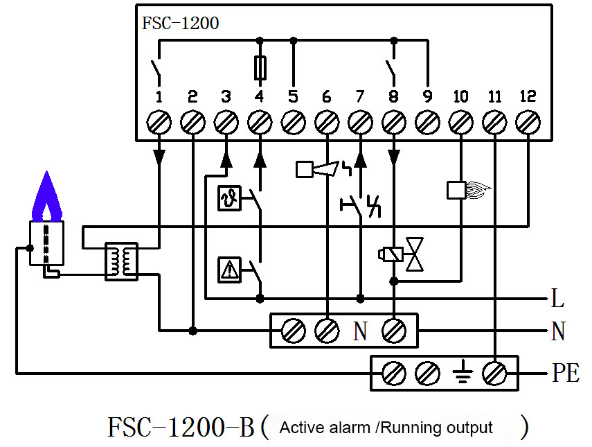
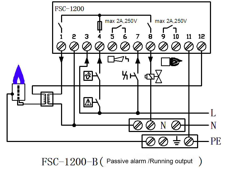
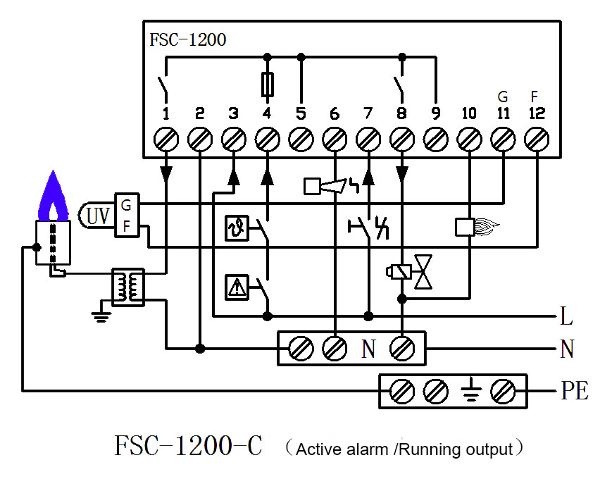
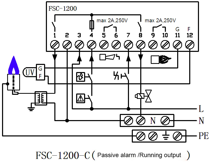

Key operation
RESET key:In the non-set status, the system can be started and stopped. In the setting status, the setting of parameters can be changed.
INFO key:Enter the setting status.
“︾”and “︽”:Make changes of parameter
* Common setting parameters:
In the power-on status ,pressing the "︽"key and “INFO” key for 3s at the same time to enter common parameters settings.Pressing the "︽" and "︾" keys to select the parameters you want to set. (See the parameter table):
Parameter | Defaults | Meaning |
dH | 1 | Number of re-ignition settings: 0~1 |
nP | 1 | Whether to detect the switch is off at power on:1; Do not detect switch disconnected:0; Detect switch disconnected. |
FA | 50 | Ignition time settings:30~60 (0.1S is the unit) |
Fd | 1 | Whether to detect flame when ignition:1: detection, 0 : No detection |
qU | Exit:press the“RESET”key to save and exit. |
Working sequence
It mainly defines the running time sequence,time definition and fault status of controller.
1.Explanation of operating status displayed
(1)Power on,the code "OF" is stopped state.
(2)Prepare, code "0".
(3)Flame simulation(T1),code "1".
(4)Ignition step (T2),code "2".
(5)Normal operation, code "3".
(6)Fault self-lock code,refer to fault type table sheet
2.Normal starting
Fault / normal: active output
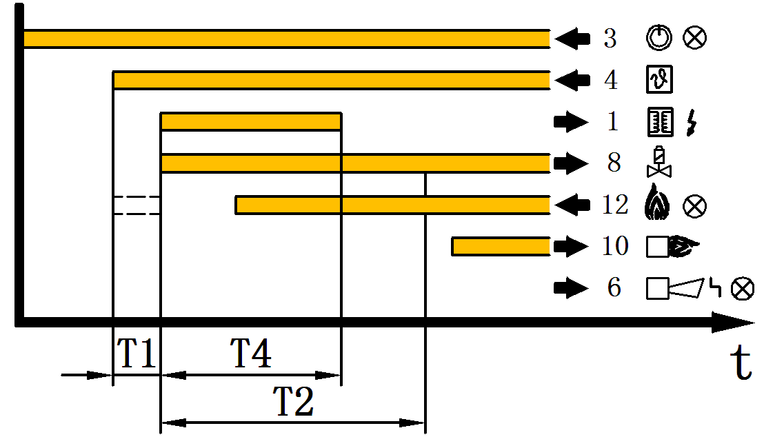
When receiving the starting signal,the flame simulation check is performed within the waiting time T1 after the controller is working, LED shows1,if no flame is detected,then enter the start safety time T2, LED displays 2 and the voltage is supplied to the gas valve and the ignition transformer at the same time,within T2 time ,after receiving the flame signal, there is an output of the signal output terminals 10, the burner starts normally and the LED is displayed as the current running status code 3.
Fault / normal: passive contact output
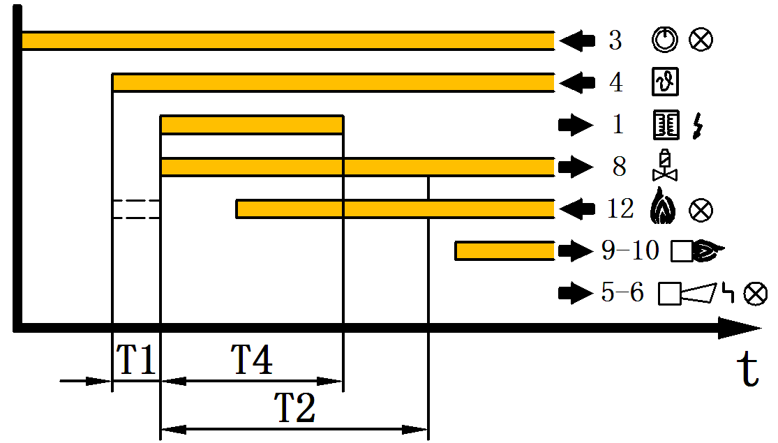
After receiving the start signal, the flame simulation check is performed within the waiting time T1 after the controller is working, and the LED displays 1.If no flame signal is detected, then enter the start safety time T2, the LED displays 2,and the voltage is supplied to the gas valve and the ignition transformer at the same time.In the T2 time, after receiving the flame signal, the signal output terminals 9 and 10 are closed, the burner is normally starting, and the LED is displayed as the current running status code 3.
3. No flame signal during start-up process
Fault / normal: active output
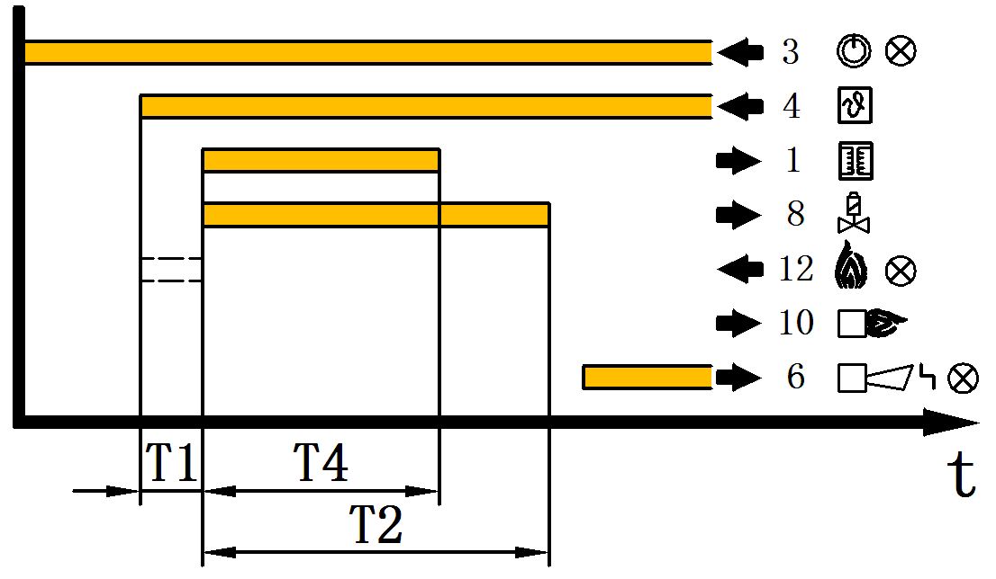
After the burner is starting normally, if the controller does not detect the flame signal within the start safety time T2 ,the fault lock occurs,there is an output of fault signal output terminal.The gas valve is open during the entire start safety time T2.LED flashes to display the fault code E2.
Fault / normal: passive contact output
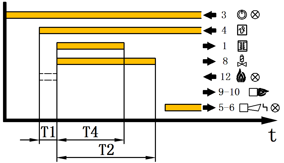
After the burner is starting normally, if the controller does not detect the flame signal within the start safety time T2 ,the fault lock occurs,fault signal output terminal 5 and 6 are closed.The gas valve is open during the entire start safety time T2.LED flashes to display fault code E2.
4.Fire signal first at startup
Fault / normal: active output
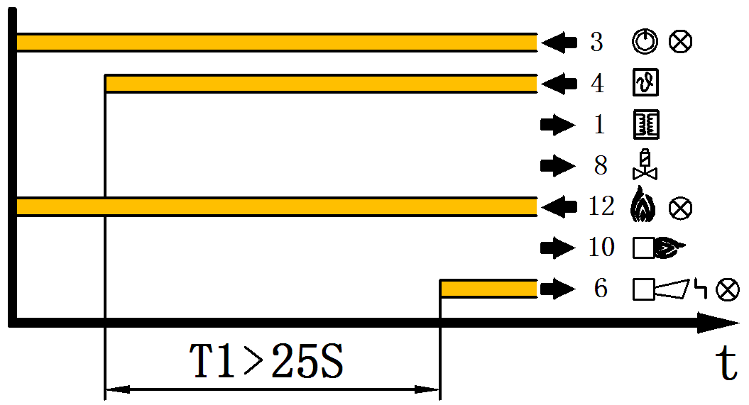
Fault / normal: passive contact output output
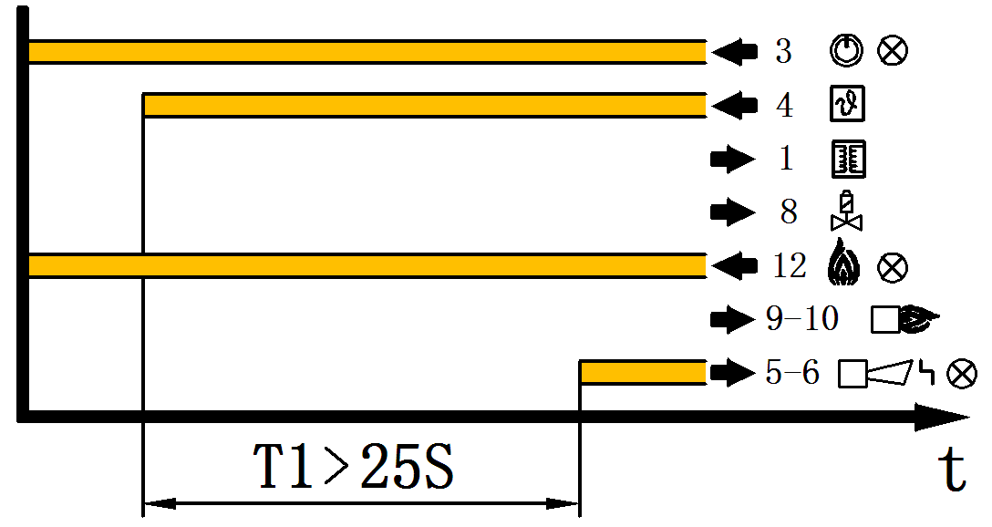
There is a flame signal when starting ,FSC-1200 performs T1 flame simulation test waiting,the maximum waiting time is 25S, if T1 flame signal disappear in the flame simulation delay time,the burner will enter the normal start-up procedure, otherwise it will enter the fault-locked state,at the same time the LED flashes to display the fault code E1.
5.Self locking or restarting after flame failure is extinguishing
The controller has self-locking and restarting function after extinguishing,which decides whether the burner will lock or restart once again after flame failure is extinguishing.
(1)Self-locking after flame failure is extinguishing
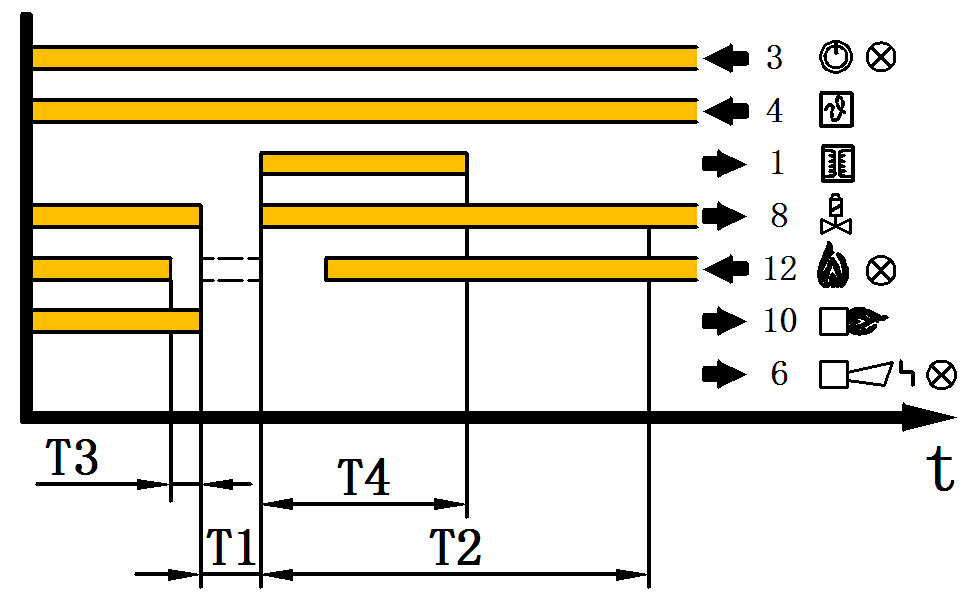
A flame failure occurs during operation,the controller enters the fault-locked status in T3 and the gas valve closes at the same time,the fault signal output terminal 5 and 6 are closed,and the LED flashes to display the fault code E3.
(2)Automatically restart once after flame is extinguishing
Fault / normal: active output
Fault / normal: passive contact output
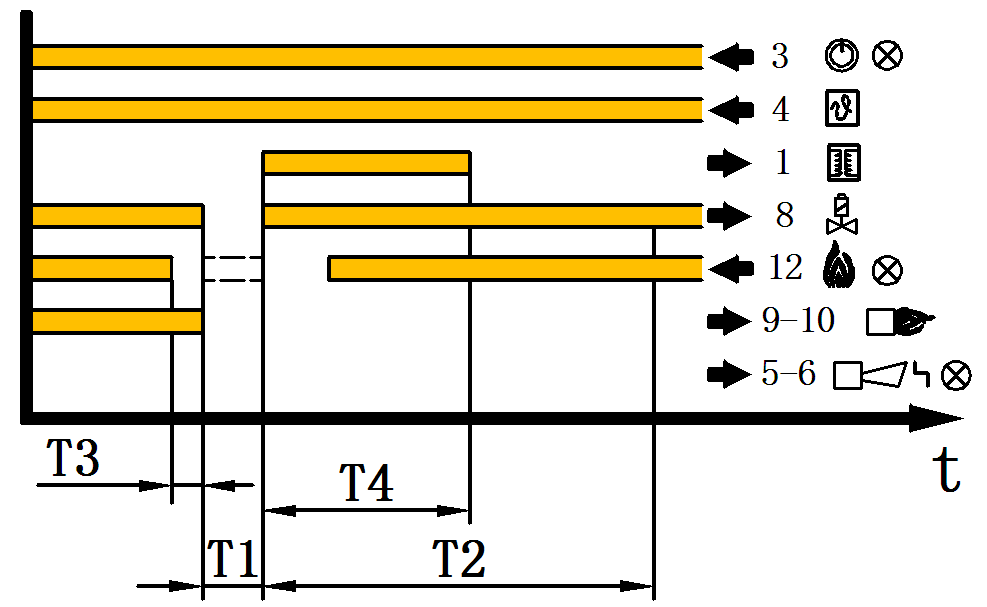
If the controller detects that the flame is extinguished after at least 2 seconds of normal operation,then the gas valve is closed during T3 time,at the same time,the fire signal output is interrupted and burner automatically restarts again once.If the burner fails to restart,it will enter the fault-lock state,LED flashes to display fault code E2.If the controller detects a flame signal during T2 time,the fire signal is output,LED displays as the current operation status code 3,the restart is completed.
6.Frequent opening and closing during T2 time
If the start signal is turn on or off more than 3 times during a same start-up process,the controller enters the fault-locked state and at the same time LED flashes to display fault code E4.
7.The time between two starts is too short
If it starts too often, the LED flashes to display the fault code E7.
8.Continuous remote reset
The continuous remote reset signal input time received by the controller cannot be longer than T7,otherwise LED flashes to display the fault code E6.The device maintains its original operating state and the fault is removed when the remote reset signal disappears.
9.Remote frequency is too high
If remote reset frequency is too high,LED flashes to display the fault code 5.The controller enters a fault-locked state, This fault can be removed only by pressing the INFO/RESET button on the controller.
10.Fault type table
Code | Fault meaning | situation | Solution |
E 1 | Self-test failed | stop | Check if the ion probe is carbonized, the insulated porcelain tube is leaking or the flame signal is detected before ignition. |
E 2 | Ignition failure | stop | remote reset or on site reset |
E 3 | Accidental flameout | stop | remote reset or on site reset |
E 4 | turn on/off action for 3 times within 15s of remote start signal | lock | On site reset |
E 5 | turn on/off action for 3 times within 10s of remote start signal | lock | On site reset |
E 6 | Remote reset signal is not recovered | Keep running | Remote reset canceled |
E 7 | Two remote start signal times <10S | stop | Disconnect remote wait to disappear andstart |

Cautions
*Installers should have professional training and practical experience.
*Please check the installation level of the product to ensure that the product is suitable for installation.
*The power must be disconnected before installation ! Must be well grounded ! Otherwise it will cause personal injury and death or equipment damage !
*Full consideration must be given to protection against accidental electric shock and ensure that personnel do not come into contact with parts that are not fully insulated!
*Please read the installation instructions carefully before installation. If the operation is incorrect, it may cause damage to the product or cause an accident.


