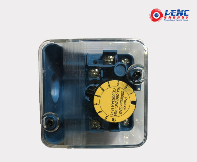
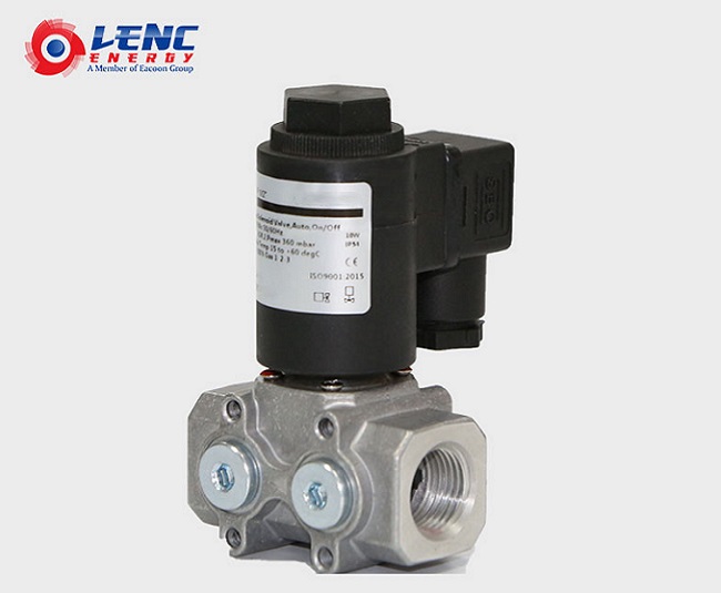
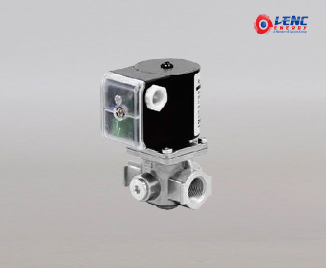
GAS PRESSURE SWITCHES --APPLICATION
The gas pressure switch is used to detect the pressure of city gas, natural gas, LP gas or air etc. When the gas pressure changes, the diaphragm of the pressure receiving part detects it and operates the switch to ON/OFF control of the external electrical circuit. These switches are widely used to detect the upper limit or lower limit pressure of gas or air to be supplied to a gas burner, or to detect the clogging of the interlock filter of a burner blower.
--TECHNICAL DATAConnection
Inlet positive pressure Rp1/4" internal pipe thread (2 x).Differential pressure Rp1/8" internal pipe thread.
Set point accuracy
-15% of the full scale (when pressure is increased) NOTE: The knob readings are approximations of the actual settings.
Contact ratings
Resistive load: 250 Vac, 5A Inductive load: 250 Vac, 3A (power factor 0.6) Minimum contact current and voltage: 50 mA, 24 Vac
Ambient temperature range
-15 -60 °CRelative humidity: max. 90% at 40 C (non-condensing)
Electrical connection
Plug connection according to PG11 or three pin plugconnector ("DIN plug") Protection against electrical shock: class I
Wire connection terminals
M3.5 screw terminals, including earth connection
--MODEL
| Model | OperatingPressure range(mbar) | Nominaloperatingdifferential(mbar) | Max. working Pressure(mbar) |
| WFA2110 | 1.0-10 | 0.4 | 200mbar, |
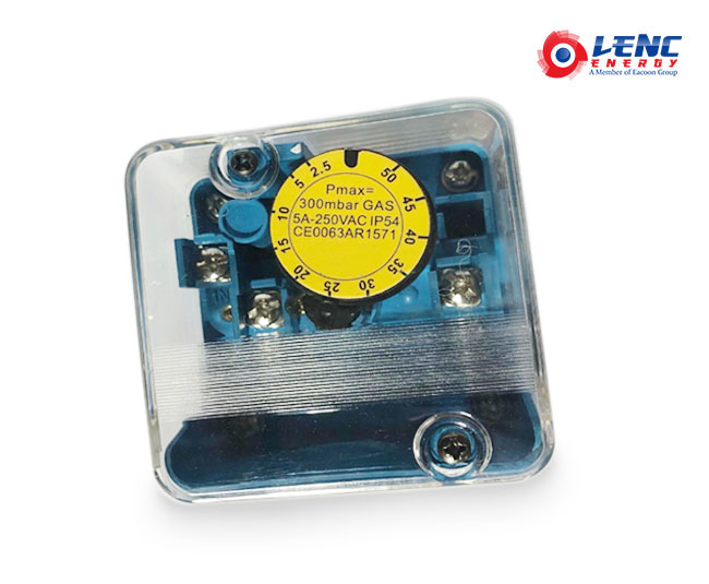
| WFA2210 | 2.5-50 | 0.6 | 300mbar |
| WFA2310 | 30-150 | 2.8 | 500mbar |
| WFA2410 | 100-500 | 7.0 | 600mbar |
Installation&Dimensions  (Fig. 1. F)
A Bracket mounting hole(3),M4 tapping,depth 5 mmB Cover screwC Dial indicatorD Conduit hole 22mm(for plug connection PG11)or,three pin(DIN) plug ConnectionE Inlet positive pressure(RP 1/4″)F Pressure test nipple(Ø 9)G Differential pressure(RP 1/8″)H Wire connection terminalJ Wire connection terminalK Wire connection terminalL Earth connection terminalM Mounting screw holes(2×4.5mm)for flanged versions
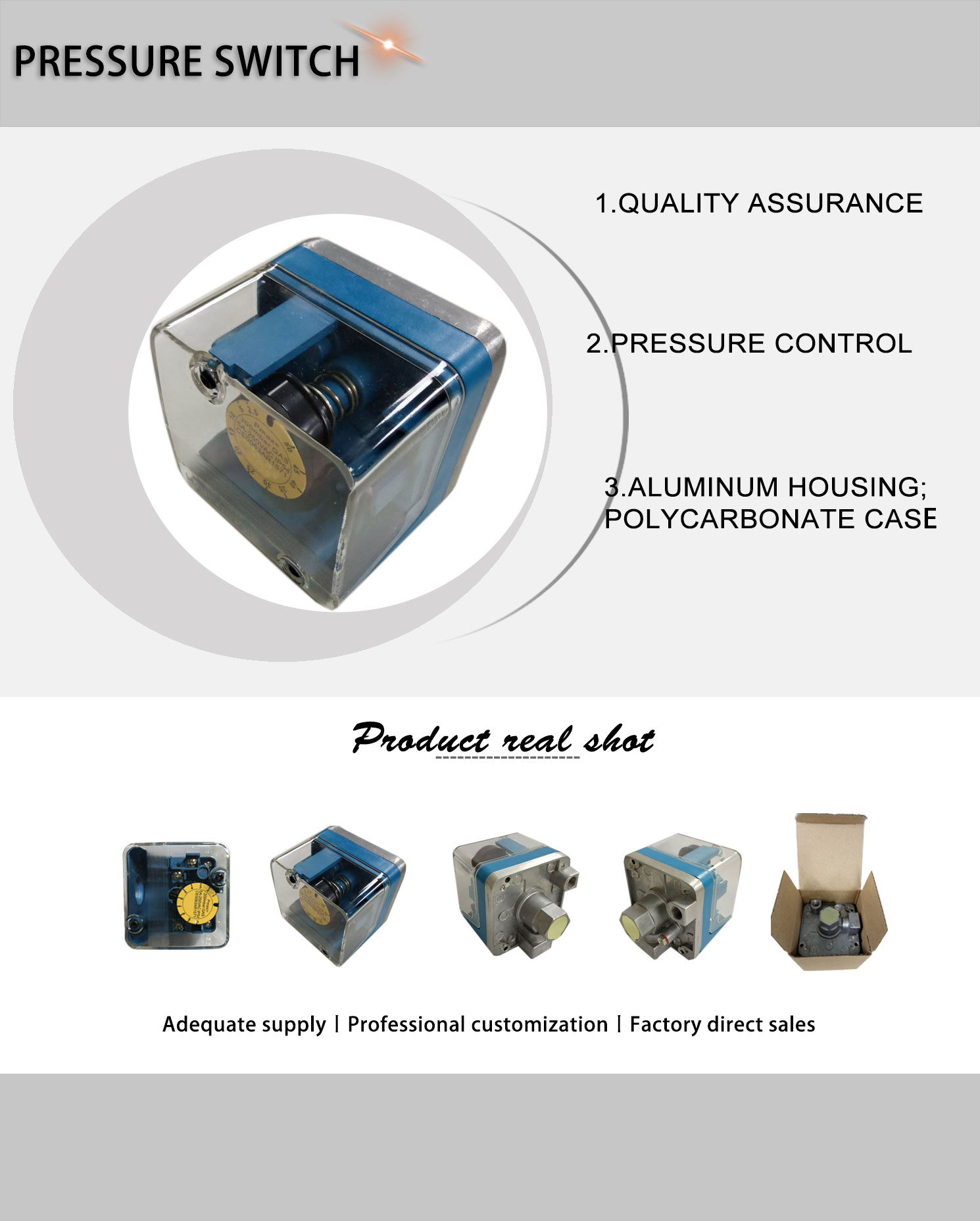
--PHYSICAL PHOTOS (Fig. 2. )
--INSTALLATION&SETTING 1.Read these instructions carefully. Failure to follow the instructions could damage the product or cause a hazardous condition.2.Check the ratings given in the instructions and on the product to make sure the product is suitable for your application.3.The installation has to be carried out by qualified personnel only.4. Carry out a thorough checkout when installation is completed.5. Electrical installation must be in accordance with local requirements
--MOUNTINGIn vertical, or horizontal plane with the setting dial facing upwards. Make sure that dirt or humidity does not get into the connection open for ventilation (G in Figure. 1.).
Regulations.
Use lead wire that can withstand 105 °C ambient.
The electrical ON/OFF operator is provided with a terminal block for electrical connections.
Wiring
Follow the instructions supplied by the appliance manufacturer. Refer to Figure 2. and 3. Connection diagram . Connection diagram
Working principle
On pressure rise, terminals between COM and NO are closed. On pressure fall, terminals between COM and NC are closed.
Pressure set point adjustment
(tolerance ± 15 % over total scale) NOTE: The knob readings are approximations of the actualsettings. 1.Remove the cover of the pressure switch.2.Turn the dial clockwise to increase or counter-clockwise to decrease the pressure set point.3.Replace the cover.
Tightness test after installation
Spray a moderate amount of good quality leak detection spray on all pipe connections.
2.Start the application and check for bubbles. If a leak is detected in a pipe connection, remake the joint.
Accurate pressure set point adjustment(tolerance < 3% over total scale)
Remove the screw from the test nipple inlet
Connect the tube of the pressure measurement device to the nipple (Fig. 1. F).
Remove the cover of the pressure switch.
Slowly release pressure of the main gas supply line until the desired value is reached.
Turn dial slowly until contact 1-3 opens and contact 2-3 closes.
Replace the cover.
Disconnect the pressure measurement device and replace the screw.
WARNING
Turn off gas supply before installation.
Disconnect power supply to the pressure switch before beginning the installation to prevent electrical shock and damage to the equipment.
Do not remove the seal over the pressure inlets,until ready to connect piping.
Switch off power supply before making electrical connections.
Take care that the wiring is in accordance with local.
*The installation and adjustment must to be carried out by qualified personnel only.


 (Fig. 1. F)