
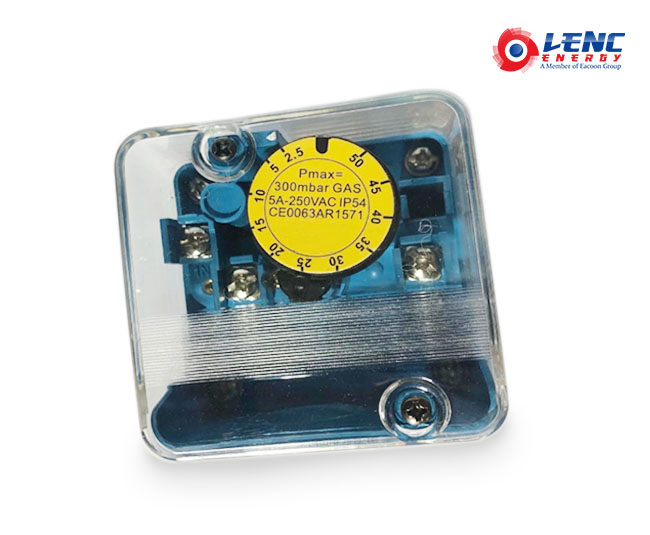
GAS PRESSURE SWITCHES --APPLICATION
The gas pressure switch is used to detect the pressure of city gas, natural gas, LP gas or air etc. When the gas pressure changes, the diaphragm of the pressure receiving part detects it and operates the switch to ON/OFF control of the external electrical circuit. These switches are widely used to detect the upper limit or lower limit pressure of gas or air to be supplied to a gas burner, or to detect the clogging of the interlock filter of a burner blower.
--TECHNICAL DATAConnection
Inlet positive pressure Rp1/4" internal pipe thread (2 x).Differential pressure Rp1/8" internal pipe thread.
Set point accuracy
-15% of the full scale (when pressure is increased) NOTE: The knob readings are approximations of the actual settings.
Contact ratings
Resistive load: 250 Vac, 5A Inductive load: 250 Vac, 3A (power factor 0.6) Minimum contact current and voltage: 50 mA, 24 Vac
Ambient temperature range
-15 -60 °CRelative humidity: max. 90% at 40 C (non-condensing)
Electrical connection
Plug connection according to PG11 or three pin plugconnector ("DIN plug") Protection against electrical shock: class I
Wire connection terminals
M3.5 screw terminals, including earth connection
--MODEL
| Model | OperatingPressure range(mbar) | Nominaloperatingdifferential(mbar) | Max. working Pressure(mbar) |
| WFA2110 | 1.0-10 | 0.4 | 200mbar, |
| WFA2210 | 2.5-50 | 0.6 | 300mbar |
| WFA2310 | 30-150 | 2.8 | 500mbar |
| WFA2410 | 100-500 | 7.0 | 600mbar |
Installation&Dimensions  (Fig. 1. F)
A Bracket mounting hole(3),M4 tapping,depth 5 mmB Cover screwC Dial indicatorD Conduit hole 22mm(for plug connection PG11)or,three pin(DIN) plug ConnectionE Inlet positive pressure(RP 1/4″)F Pressure test nipple(Ø 9)G Differential pressure(RP 1/8″)H Wire connection terminalJ Wire connection terminalK Wire connection terminalL Earth connection terminalM Mounting screw holes(2×4.5mm)for flanged versions
--PHYSICAL PHOTOS (Fig. 2. )
--INSTALLATION&SETTING 1.Read these instructions carefully. Failure to follow the instructions could damage the product or cause a hazardous condition.2.Check the ratings given in the instructions and on the product to make sure the product is suitable for your application.3.The installation has to be carried out by qualified personnel only.4. Carry out a thorough checkout when installation is completed.5. Electrical installation must be in accordance with local requirements
--MOUNTINGIn vertical, or horizontal plane with the setting dial facing upwards. Make sure that dirt or humidity does not get into the connection open for ventilation (G in Figure. 1.).
Regulations.
Use lead wire that can withstand 105 °C ambient.
The electrical ON/OFF operator is provided with a terminal block for electrical connections.
Wiring
Follow the instructions supplied by the appliance manufacturer. Refer to Figure 2. and 3. Connection diagram . Connection diagram
Working principle
On pressure rise, terminals between COM and NO are closed. On pressure fall, terminals between COM and NC are closed.
Pressure set point adjustment
(tolerance ± 15 % over total scale) NOTE: The knob readings are approximations of the actualsettings. 1.Remove the cover of the pressure switch.2.Turn the dial clockwise to increase or counter-clockwise to decrease the pressure set point.3.Replace the cover.
Tightness test after installation
Spray a moderate amount of good quality leak detection spray on all pipe connections.
2.Start the application and check for bubbles. If a leak is detected in a pipe connection, remake the joint.
Accurate pressure set point adjustment(tolerance < 3% over total scale)
Remove the screw from the test nipple inlet
Connect the tube of the pressure measurement device to the nipple (Fig. 1. F).
Remove the cover of the pressure switch.
Slowly release pressure of the main gas supply line until the desired value is reached.
Turn dial slowly until contact 1-3 opens and contact 2-3 closes.
Replace the cover.
Disconnect the pressure measurement device and replace the screw.
WARNING
Turn off gas supply before installation.
Disconnect power supply to the pressure switch before beginning the installation to prevent electrical shock and damage to the equipment.
Do not remove the seal over the pressure inlets,until ready to connect piping.
Switch off power supply before making electrical connections.
Take care that the wiring is in accordance with local.
*The installation and adjustment must to be carried out by qualified personnel only.
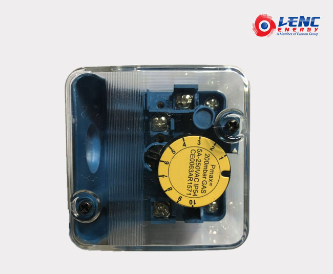
Connection
2*Rp1/4 Inlet Positive pressure internal pipe thread
1*Rp1/8 Differential pressure internal pipe thread
Connection
2*Rp1/4 Inlet Positive pressure internal pipe thread
1*Rp1/8 Differential pressure internal pipe thread
Material
Aluminum housing; Polycarbonate Case
Medium Temperature
-15 – 80℃
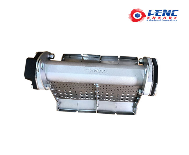
Characteristics
1. For direct fired fresh air heating applications
2. Operates economically (100 % thermal efficiency) and installs easily
3. Burns clean and odor-free with most gaseous fuels, meeting or exceeding most known standards for direct-fired make-up air and space-heating applications
4. Modular design configured within your duct for optimal temperature distribution
5. No need for a combustion air blower
6. Extremely low maintenance cost thanks to robust design (no moving parts) and high quality materials
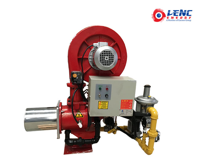
Energy-efficient Burner
100,000-200,000 kcal/h (116-233 kw/h)
300,000-400,000 kcal/h (349-465 kw/h)
500,000-600,000 kcal/h
700,000-800,000 kcal/h
900,000-1000,000 kcal/h
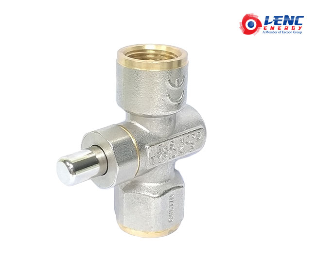
Body Material:Press-forged nickel-plated brass
Thread Connections:Rp1/4,3/8,1/2
Fluid:Gas,Air
Max Pressure:5bar
Temperature:-10°C-+70°C
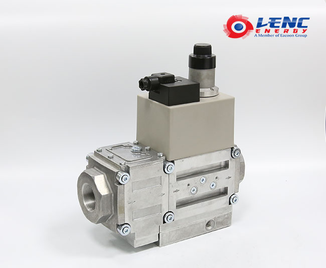
Description:
Gas MultiBloc/Functicon Solenoid valve intergrades filter, regulator, valves and pressure sensor in one compact fitting.
// Filter
// One regulator and two valves: BO1
// One valve is fast opening and one valve is slow opening
// Solenoid valves up to 360mbar as per DIN EN161 Class A Group 2
// Sensitive setting of output pressure by regulator as per DIN EN88 Class A Group 2
// High flow rate at low pressure drop
// DC Solenoid drive interference degree N
// Main Volume/Flow restrictor at V2
// Flange connection with pipe threads as per ISO7/1
// Applicable to gases, such as natural gas, methane, LPG and so on
// Blue signal light indicates working status
// Simple mounting, compact and light weight
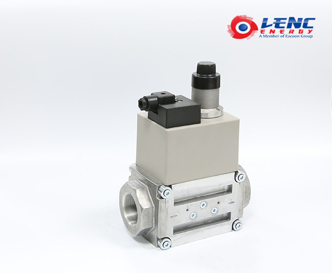
Description:
// The dual modular solenoid valve consist of two safety shutoff valves in one compact fitting:
// Solenoid shutoff valves as per DIN EN161 Class A Group 2
// Two A valves in one compact body
// Two valve blocks
// High flow rate
// Max pressure 500mbar
// Fast closing
// Fast or slow opening, with fast initial gas allowance
// Main volume adjustable
// Flexible combination between flange and thread
// Applicable to gases, such as natural gas, methane, LPG and so on
// Blue signal light indicates working status
// Compact and light weight
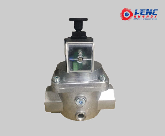
Opening Time: less than 1 second
Closing Time: less than 1 second
Numbers of operations: 20 per minute.
DN10-25 360mbar:DN32-50 200mbar
Max working Pressure: 200/360mbar
By-pass ports are set on both sides of the valves,
with diameter of G1/4”
Inside filter net
Protection: IP54
Sealing material: chemigum
Body material: aluminum alloy
Pressure steel spring AISI 302.
The ambient temperature: -15℃- 60℃
Coil temperature: 65℃
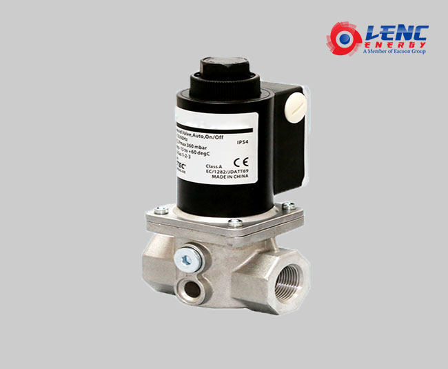
Opening Time: less than 1 second
Closing Time: less than 1 second
Numbers of operations: 20 per minute.
Max working Pressure: 200/360mbar; DN32-50 200mbar
By-pass ports are set on both sides of the valves, with diameter of G1/4”
Built-in filtering
Protection: IP54
Sealing material: Nitrile rubber
Body material: aluminum alloy
Pressure steel spring AISI 302.
The ambient temperature: -15℃- 60℃
Coil temperature: 65℃
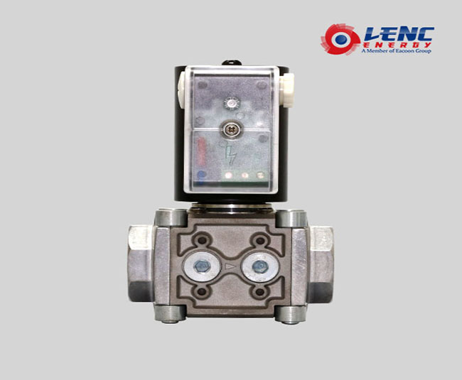
Opening time <1 seconds
Closing time <1 seconds
Maximum operating frequency: 20 times per minute
Maximum working pressure: 500 mbar
Equipped with G1/4 aperture bypass hole
Built-in filter
Protection level :IP54
Sealing material: Nitrile Rubber
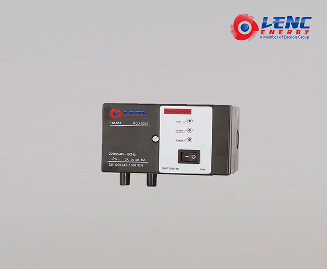
Related parameter:
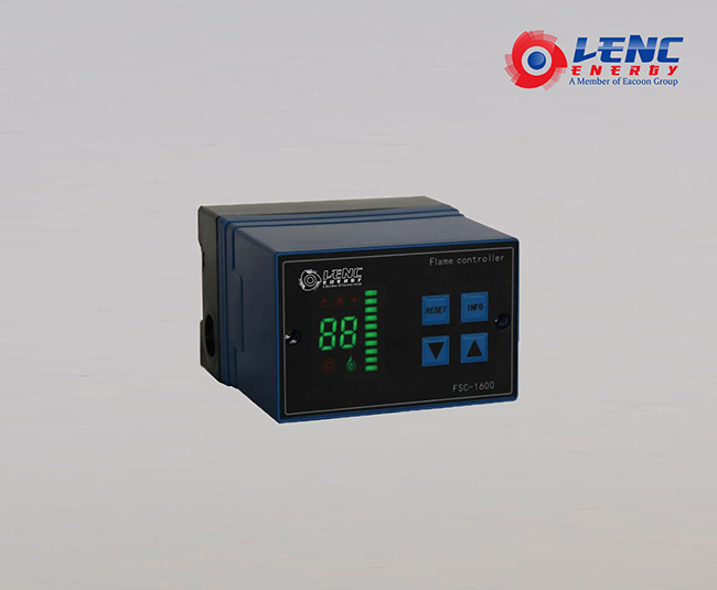
Rated voltage:AC220V~230V 50/60Hz(-15%~+10%)
Environment temperature:Single equipment installation:-20~+60°C
More than two sets of equipment installation:-20~+45°C
Environment humidity:lower than 90%RH (can’t be used in condensation environment)
Shockproof performance:each side of x,y,z is shock-resistant for 0.5G and the frequency is 10-150Hz
Insulation class: when the DC current is 500V, the resistance of the terminal to ground is higher than 50MΩ.
Insulator strength: when the AC current is 1800V for 1 second or AC 1500V for 1 minute, the terminal-to-ground leakage is lower than10mA(except for flame detector terminals)
Design life: 100,000 times normal operation(In the case of meeting all external conditions)
Terminal load:5A
Size:Width 126.5 x height 76 x thickness 86mm
Weight: Net weight is about 500G
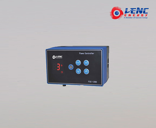
The main technical parameters
Width*thickness*height:126*94.5*92.5mm
Input voltage:AC 220V/24V 50/60Hz
Lonic bar cable length:75m (maximum)
Protection level:IP54
Environment temperature:-20℃ ~ +65℃
Environment humidity:< 95%
Operating life:>100 thousand times
The maximum current of driving the gas valve:1A ;Power factor:1
The maximum current of driving the ignition transformer:2A ;power factor:0.2
The maximum current of the output terminal:2A AC Voltage:250v
Application:
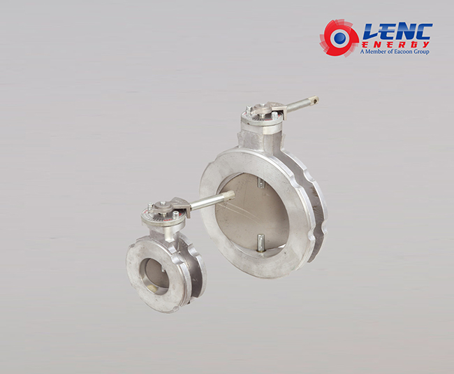
Butterfly valves are used for regulating and cutting off the medium flow in the pipeline
suitable for conveying pipelines of corrosive and non-corrosive fluid medium in furnace,coal gas, natural gas, LPG, city gas, hot&cold air, chemical smelting and power generation environmental protection engineering systems
1. simple and compact structure with light weight, easy to assemble and disassemble .
2. low torque with 90°, easy to open and close with high speed.
3. small flow resistance, flow curve goes in slope line, power saving.
4. customised products according to specific materials requirements of the client, suitable for various gases and environment.
Technical parameter
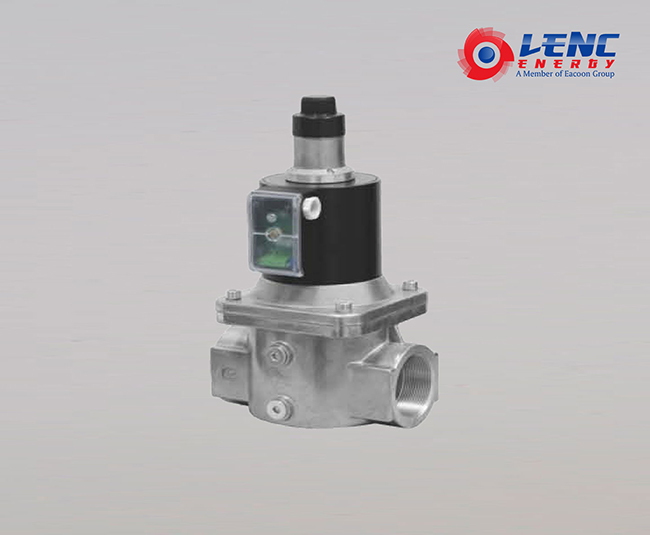
Opening time 1-30 seconds adjustable
Closing time < 1 second
Maximum operating frequency:20 times/min
Maximum working pressure:
DN 10 - 25 360 mbar;DN 32 - 50 200 mbar
With G/4 aperture bypass hole
Built-in filtering
Protection level:IP54
Technical parameter
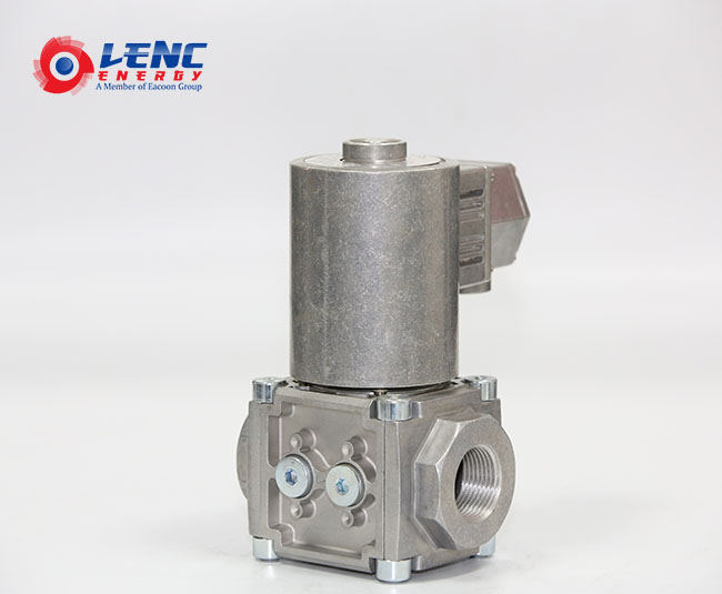
Opening Time: less than 1 second
Closing Time: less than 1 second
Maximum operating frequency: 20 times per minute
Maximum working pressure: atmospheric pressure 20-25 360 mbar; high pressure
By-pass ports are set on both sides of the valves, with diameter of G1/4”
Inside filter net
Protection: IP54
Sealing material: nitrile rubber
Body material: aluminum alloy
Pressure steel spring AISI 302.
The ambient temperature: -15℃- 60℃
Coil temperature: 65℃
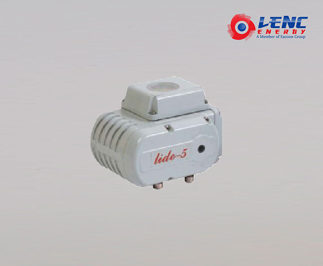
Features
■High performance, high strength
■Aluminum alloy die-cast, beautiful and smooth, light and compact
■Can be installed at any angle, tightly connected with the valve
■Built-in overheat protection function, Double limit and overload protection
■Can be manually operated using the supplied crank handle after power is turned off
Application
Through the external power supply or adjusting the power supply switching signal output by the meter, the output shaft can be used to make the corresponding angular displacement to drive the valve opening/closing actions, then achieving the adjustment of the liquid gas flow.
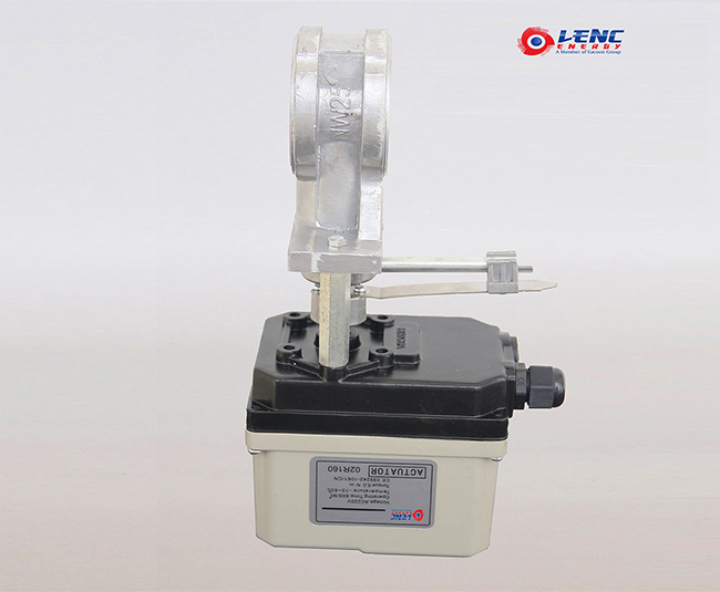
LC-SM-10 Series Rotary Electric Actuator is specially used in controling of 0-90 °or 0-160 ° Corner travel. Available used for operating and controlling Drive damper butterfly valves, Gas linear valves and Small ball valves etc.
Installation Environment
■This product can be installed indoors / outdoors
■This product is an non-explosion-proof item, please avoid used under the flammable, explosive and other similar environments
■Protection measures need to be installed, if the long-termraining, oil &other flying objects, and especially under the impact of direct sunlight environments.
■Please reserve space for maintenance such as wiring and manual operation etc., The environmental conditions temperature is in the range of -30 to +60°C.
Installation Environment
■Pay attention to the medium temperature when selecting the valves, If the medium temperature is too high, it will be transmitted to the body, which reduces the service life.
■When the temperature of the medium is too high, the fixed support connected to the valve can reduce the heat conduction.
■Medium temperature <80 °C, selecting standard support
■Medium temperature >80 °C, selecting heightened standard support
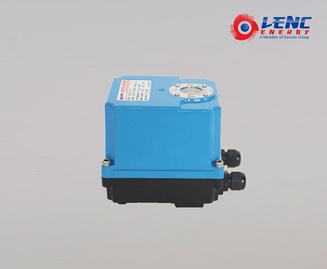
Supply Voltage:220VAC 24VAC 110VAC 50/60Hz
Control Signal:4-20mA 1-5V 0-10V
Running time:55s(90°) 30s (90°) 15s(90°)
5s(90°) 3.3S(90°)
Output shaft torque:55s(40Nm) 30s(25Nm) 15s(15Nm)
5s(5Nm) 3.3S(5Nm)
Operating environment: -30℃~+60°C
Protection Class:IP54 IP67 (Optional)
installing direction: 360°installed at any angle
Corner travel: 0-90° adjustable or 0-160° adjustable
Motor Power: 15W
Insulation Resistance: 100MΩ/500VDC
Compressive Strength: 1500VAC/1min
Net Weight : 3.2Kg
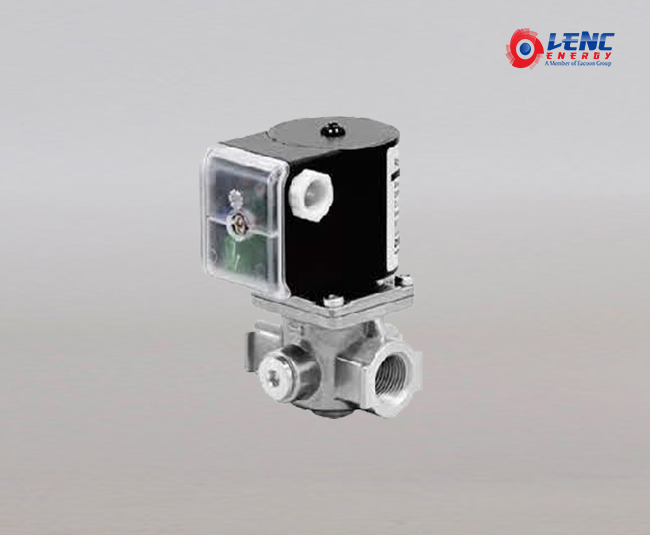
Technical parameter :
LVC-FS series solenoid valve
Opening time < 1 second
Closing time < 1 second
Maximum operating frequency: 20 times/min
Maximum working pressure: DN10-25 360mbar;DN32-50 200mbar
With G1/4 aperture bypass hole
Built-in filtering
Standard and certification:
"A" standard
Meets European gas standards
CE certification
Electrical specification
Rated voltage:50/60Hz,230Vac、110Vac、24VDC(And other specific)
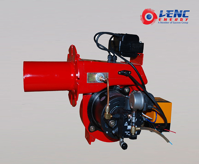
Characteristic:
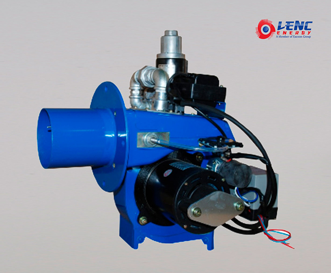
1.Beautiful appearance,reliable structure.
2.High P-Q characteristic ,strong adaptability.
3.Directly ignition mode.
4.Easy to inspect and maintain.
5.Safety flame monitoring system.
6.Stable performance,reliable operaton.
Application
Suitable for small boilers and drying heating equipment.
Copyright © Guangzhou Liancheng Energy Technology Development Co. Ltd. All Rights Reserved. Sitemap | Technical Support:
